Showing posts with label Free Plans. Show all posts

Friday, December 3, 2021

Manson Hot Air Engine - Free Plan


I got interested in hot air engines earlier this year and wound up building the popular Moriya model designed by Dr.  James Senft.  I got lots of help and encouragement from the guys on the Home Machinist forum.  There's a pretty lively discussion of the entire build here, including a link to a copy of Dr. Senft's original plans.

Sometime later I got interested in the Manson-style hot air engine, mostly due to its simplicity.  Surprisingly, I wasn't able to find a complete set of drawings for a Manson engine, so I tried to come up with an original design.  My first attempt was similar in a lot of ways to the Moriya engine, but it didn't run very well.  The next effort was kind of a cross between the partially complete plans found here and the build log for yet another example found here.  It ran much better than the first attempt, but still wasn't great.  But once again, the guys on the Home Machinist forum came through with some great hints for improvement, and with them, a third engine very similar to the second one ran like a champ.  There's even a video:


The Plans

This file contains a Fusion 360 model for the third version, 2D drawings based on that model, photos of most of the parts, and a few miscellaneous notes.  If you have any questions or comments about these plans, I'd love to hear them, either here or in a comment attached to the video mentioned above.

Monday, July 23, 2018

Rolling Stool - Free Plan

I always wanted one of those five-legged stools like the doctor scoots around on when he has you trapped in his little examination room.  So I built one, using some beetle kill pine from the rack at Home Depot and some swivel casters from Harbor Freight.  It looked like this:


I figured from the beginning that sitting on it would tend to pry the legs loose from the little hub-like piece near the bottom, so I was very careful to attach the legs firmly to the hub.  So far, so good.  So far, so good, that is, until one day the hub itself split in two as I sat down on the stool.  Oops.  Butt, meet floor!

Design attempt #2 worked out much better.  It looks like this:


With the legs transmitting the load directly from the seat to the wheels, it's not trying to rend itself asunder when you sit on it.  Better materials (hardwood and metal tubing) didn't hurt, either.

Free Plan

This PDF file contains detailed drawings for all of the stool's parts as I built them.  There's also a SketchUp model here.  I made all of the wooden parts from oak, and the metal parts from 1/2" thin-wall electrical conduit.  I glued up some 3/4" boards to get the required thickness for the wooden parts.  I also had to glue together a couple of pieces edgewise to get a board wide enough for the seat.

Here are some hints that might be useful if you want to make one of these for yourself:

The Metal Parts

The metal parts are all straight sections of 1/2" thin-wall electrical conduit, so just cut them to length according to the plans.  If you want to paint the conduit, now is a good time so the paint can dry while you make the wooden parts.

The Seat

After you've cut out the seat, you'll want to put a slight round-over on at least the top edge so it doesn't cut into your leg when you sit on the stool.  Also, you'll need to accurately mark the center of the bottom surface for reference later when installing the legs.

The Other Wooden Parts

The hub, the feet, and the connectors are all drilled to accept parts made from conduit.  These holes need to fit the conduit fairly closely.  Since you probably don't have a 0.705" drill in your toolbox, make one by carefully grinding down both sides of an old 3/4" spade bit until a test hole in a scrap of wood fits the conduit.  Aim for a snug fit.

After cutting out the hub and the feet, carefully lay out the locations of the holes, then use a V-block for support while drilling with the modified spade bit.  Be careful to stop when you reach the depth indicated on the plans.

For the connectors, lay out the holes as before, then use the connector drilling fixture shown in the plans to hold the connectors at the proper angle for drilling.

Assembly

Start by gluing five of the connectors to the five feet, as shown in the plans.  Each connector should be centered on the top surface of a foot, with the hole in the connector aligned with the middle hole in the foot.

Next, insert the five spokes into the hub, as shown here.  (Click on any of the images for a larger view.)  Make sure the spokes are fully seated within the holes in the hub, then drill pilot holes halfway through the bottom of the hub and into each spoke.  Install a 1" sheet metal screw into each hole to keep the spokes from twisting or coming out of the hub.

Now assemble the feet and braces together with the hub and spokes as shown.  This may be kind of tricky because it all has to happen at once.  Start by positioning the parts so that all the braces and spokes extend just a short distance into the holes in the feet.  Then work your way slowly around the assembly from one foot to another, gradually pushing the metal parts into the holes until they are all fully seated.

Next, turn the entire assembly upside down on a flat surface so that the feet are all in the same plane.  Check one more time to make sure the braces and spokes are all fully seated within the holes in the feet, and use clamps and/or weights as needed to force the connectors against the flat surface.  With everything in position, drill pilot holes and pin the spokes into the feet using sheet metal screws as before.  Important: Here, the heads of the screws must be sunk into the bottom surfaces of the feet so they don't interfere with the installation of the casters later.  You don't need to pin the braces.

In the next step, you will complete the assembly and glue the five remaining connectors to the bottom of the seat.  To make this easy, it's helpful to install some temporary guides on the seat to help position the connectors correctly.  Starting from the center point you marked earlier, draw five radial lines, 72 degrees apart, on the bottom of the seat, as shown here:


Next, draw five 3" x 1-1/2" rectangles to represent the footprints of the five connectors.  These rectangles should be centered on the five radial lines, and positioned 1/4" in from the edge of the seat.  Finally, use hot glue or small brads to temporarily attach small strips of wood along two edges of each rectangle, as shown.  The connectors will register against these strips in the next step.

Now insert the legs into the connectors on the feet and slip the remaining connectors onto the top ends of the legs as shown.  As always, make sure the metal parts are fully seated into their respective holes.  Apply glue to the seat and the connectors, align the connectors with the temporary guides, and clamp the connectors to the seat.  Once the clamps are in place, remove the temporary guides and wait for the glue to dry before removing the clamps.

Install some casters to the bottom of the feet, and you're done!

Monday, February 23, 2015

Biesmeyer-Style Bandsaw Fence - Free Plan

I have a Taiwanese clone of the Delta 14" bandsaw that I bought used without a fence.  That didn't bother me too much at first, because I thought that I would be using it to cut curves most of the time, and that when I did need a fence, I could just clamp a board to the table.  But then I found out how useful a bandsaw is as a ripping machine and for certain kinds of joinery, and how tedious it is to accommodate drift using the clamp-a-board-to-the-table method.

I needed a real fence.

I thought about building the shop made fence described by Patrick Sullivan in Fine Woodworking #210.  But when I looked at it closely, the design seemed overly complicated to me.  So I set out to build something simpler that would still get the job done.  After a couple of false starts, I eventually came up with the Biesemeyer-style fence described here.

I started with a piece of 1-1/4" x 1-1/4" x 1/8" 6063-T5 aluminum channel for the rail.  I cut one leg off at 13/16" as shown in this drawing.  I then drilled it to match the mounting holes on my bandsaw table and cut a little notch to match the bandsaw's miter slot.

Then I made the "slider" shown in this drawing.  It rides to the left and right along the rail and clamps in place with a little bolt.  The longish piece on the bottom of the slider registers against the rail to align the slider, while the shorter piece carries a T-nut for the bolt that clamps the slider to the rail.  You could use a threaded insert instead of the T-nut if you want.  If you look carefully, you'll see a little piece of bent sheet metal that prevents the slider from marring the aluminum rail when you crank down on the bolt.  I called this thing the "rail protector", and it's shown in this drawing.


There are also two T-nuts in the holes on top of the slider.  These receive a couple of bolts that hold the base of the fence to the slider.


This drawing shows the base of the fence itself.  It's cut out on the left side to clear the bandsaw's yoke when the fence is positioned towards the left side of the bandsaw table.  The hole and the curved slot nearest the operator accommodate bolts that attach the base to the slider.  The curved slot allows the base to rotate in order to adjust for drift.

The other holes in the base have threaded inserts or T-nuts that allow attachment of the auxiliary high fence shown in this drawing.  It can be installed in either of two orientations for resawing or to accommodate various workpiece thicknesses.


You might want to use star knobs instead of the bolts that I have shown for the clamp bolt in the slider and the bolts that attach the base to the slider.  You might also might want to make the slider and base out of aluminum instead of wood!


Saturday, November 12, 2011

Yet Another Box Joint Jig - Free Plan

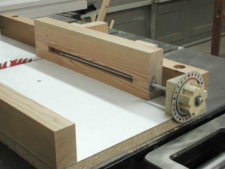
Like most everyone in the world, I've posted a few of my projects on LumberJocks.com. So far, the most popular one has been this box joint jig. The basic idea came from Matthias Wandel's original box joint jig, but instead of a crank like Matthias used, I put a knob with a dial on mine to move the workpiece back and forth. I thought this was a little bit simpler and a little more versatile than Matthias's version with the crank.

The jig is built by adding a sliding carriage to the rear fence of a standard crosscut sled. To use it, you clamp the your workpiece to the sliding carriage, and then turn the knob to precisely position the carriage for each successive cut. Each mark on the dial represents 0.002" of movement, so with a little planning, you can make any sort of box joint you want. More on that later.

The Details

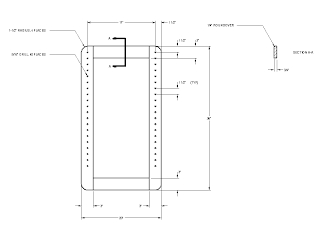
If you want to build one of these yourself, the following pictures link to drawings that give the dimensions of the jig as I built it.  The table on my saw is about 27" wide, and the blade is about 16" from the left side of the table.  If your saw is substantially different, you may need to adjust the dimensions of the jig to suit your saw.  In particular, you must make absolutely sure that your saw cannot cut into the jig's metal lead screw.

Rear Fence
Bearing Block
Carriage
Lead Screw
Dial

Building the Jig

To build the jig, start by making a standard crosscut sled for your table saw.  Make the rear fence 2-1/4" tall and 1-1/2" thick, as shown in the first drawing above.  Make sure the rear fence is square to the saw blade.  This video shows a quick and straightforward way to square the fence on a crosscut sled.

Next, find a bearing to support the end of the lead screw near the dial.  Ideally, the bearing should have an inner diameter of 1/4" to match the 1/4-20 threaded rod used for the lead screw.  If you happen to have a bearing with a larger inner diameter, you can make it work with a bushing as shown in the photo nearby.  My bearing happened to have an outer diameter of 1-3/8".  Anything smaller than 1-1/2" or so would work.

When you have found a suitable bearing, make the bearing block shown in the second drawing above, except that the hole should fit your bearing.  Center the hole in the bearing block, and size it so that your bearing fits tightly into the hole.  Attach the completed bearing block to the left end of the crosscut sled's rear fence, as shown in the first two photos above.

Now make the carriage as shown in the third drawing above.  Use extra care when making the little hooks that ride over the fence.  You want the carriage to slide freely on the fence, but with as little play as possible.  There's nothing special about the big mortise that houses the lead screw;  it was just easier for me to make it that way than to try to drill a long hole lengthwise through the carriage.  (I guess there's also some comfort in being able to see the lead screw, in order to make double dang sure that you're not going to cut into it with the saw blade.)  Embed a 1/4-20 nut in the end of the carriage as shown in the drawing and in the first photo above.

Important:  When you have the carriage complete, add a block of wood to the backside of the rear fence as shown in the second photo above.  The purpose of this block is to protect your fingers from the saw blade at the end of each cut.  The block must fully enclose the blade as it comes through the back of the fence.  You will need to notch the top corner of the block as shown to allow the carriage to slide freely back and forth.  Do not use the jig without this block in place.

To make the dial, click on the image above to open a .PDF file that contains a full sized image of the dial.  When you print the image, the diameter of the dial should be 3-1/2".  Paste the printed image onto a piece of 1/8" plywood (or something similar), cut out the circle, and drill a 1/4" hole in the center.  Next make a knob of some sort, and cut the lead screw to length from 1/4-20 threaded rod stock.  Attach the knob and the dial securely to one end of the lead screw.  The knob and the dial must not be allowed to rotate on the lead screw.

Next, thread the free end of the lead screw through the bearing and install a washer and a pair of jam nuts as shown in the photo nearby.  When you're using the jig, you'll need to apply slight pressure to the carriage to ensure that the jam nuts ride tight against the bearing.  If you want, you could add some sort of spring arrangement to take care of this automatically.

Finally, position the carriage over the rear fence and thread the lead screw into its embedded nut by turning the dial.  Check one last time that your saw can't cut into the lead screw, and you're ready to go.

Measuring Your Kerf Width

With the jig complete, you can now make precisely spaced crosscuts by clamping your workpiece to the carriage and then turning the dial to move the workpiece after each cut. Before you can do much of anything useful, though, you need to know the width of the kerf that's taken by your particular saw blade. If you have a dial caliper or one of those fancy electronic ones, this is fairly easy to measure, as follows:
  1. Use your saw to rip a piece of scrap two or three inches wide. Make sure the edges are both straight and parallel to one another, then use the caliper to take a precise measurement of the width of the scrap.
  2. Rip the scrap down the middle into two pieces.
  3. Reassemble the two pieces next to each other, and measure their combined width.
  4. Subtract the combined width of the two pieces from the width of the original piece. This difference is the width of the kerf that was taken by your saw blade.
If you don't have a caliper, you will have to take as good a guess as you can, then make some trial and error adjustments later when you actually go to use the jig.

Cutting a Simple Box Joint

Probably the simplest box joint to cut is one where the fingers are the same width as the saw kerf.  That would be roughly 1/8" for a normal blade, or whatever you want if you are using a dado stack.  In any case, the joint involves a series of cuts that are evenly spaced by twice the width of the saw kerf.  So let's suppose that your kerf is 0.132" wide.  That means you want to move the carriage by twice that amount, or 0.264", after each cut.  So how do you do that?

If you're a math whiz (or maybe a machinist), you might realize that each dot on the dial represents 0.002" of carriage movement, and that the numbers on the dial represent thousanths of an inch.  From that, you could figure out how far to turn the dial based on the numbers, but doing so would involve some error-prone arithmetic for every single cut.  Fortunately, there's an easier way that's based on the pattern of colored arcs and dots on the dial.

Here's all you have to remember:
  • Rotating the dial by one dot's worth moves the carriage 0.002".
  • Rotating the dial by one arc's worth moves the carriage 0.010"
  • Rotating the dial one full turn moves the carriage 0.050"
So, in our example, to move the carriage by 0.264", you would turn the dial five turns to move it by 0.250", then one arc to bring it to 0.260", then two dots to reach 0.264".  So "five turns, one arc, and two dots" is all you have to remember (or write down), and it's the same for every cut.  This is actually a lot easier to do than it is to explain.  Once you've played with it a while, you'll do it without thinking.

Cutting More Complicated Joints

With the jig, you're not limited to any particular finger width or spacing, although more complicated joints do involve a little bit of planning.  But the fundamental process is straightforward:  Figure out how you need to space your cuts, turn the dial to put the workpiece exactly (!) where you want it, and have at it.

Wednesday, August 24, 2011

Folding Step Stool - Free Plan

This is my take on a folding step stool design that's been around forever. My grandmothers each had one like it in their '50s kitchens. Today, fifty years later, you can point, click, and have a new one delivered to your door from any of a number of online vendors.

 Many of these vendors describe their stools as "Amish". I'm not sure if that means the design is somehow Amish, or if the stools are being made by Amish builders, or what. In any case, they're pretty handy, and a heckuva lot safer than that upside-down Home Depot bucket you've been climbing on to reach the top shelf where Grandma keeps her gin.

Resources

 If you want to build one of these yourself, the following two pictures link to drawings that give the basic dimensions for the stool:

The Stool

The Steps


Thanks to John Sprofera, you can also download a simple SketchUp model of the stool by clicking here.

There's also a more detailed SketchUp model here.  It shows the joinery in more detail, and has dimensioned drawings of all the individual parts.  This file contains the same set of drawings, but in PDF format if that's more convenient for you than SketchUp.

Construction Notes

I made my stool from oak, and finished it with several coats of wipe-on polyurethane. I used through mortise and tenon joints between the legs and the transverse stretchers, and floating tenons to join the legs with the side stretchers. I attached the seat and the steps with screws running up from underneath. These screws are set into oversize holes to allow the seat and the steps to expand and contract across their widths with changes in humidity. This precaution probably wasn't necessary for the steps because they are so narrow, but probably was for the seat.

Almost any wood would work for this project, although it might be a good idea to use a hardwood dowel for the step pivot, even if the rest was made from softwood. Likewise, any number of joinery options could work as well.

While there's nothing magical about this particular design, it is very important to get the shape of the side pieces that hold up the steps correct, as well as the location of the pivot pin. If you don't, the step assembly might hit one of the stretchers when it shouldn't. Be sure to keep this in mind if you decide to modify the plans for some reason.
 
 The other thing to watch out for is the grain direction in the side pieces that hold up the steps. It's best to orient the grain as shown in the first picture above. Unfortunately, this makes it a little bit tricky to lay out the shape of these parts. To solve this problem, I made a full-size template out of 1/4" MDF. Then I traced around the template and cut out the parts slightly oversize with a band saw. Then I attached the template to the rough blanks one at a time and trimmed them to their final shape using a router with a flush trim bit.

Sunday, March 20, 2011

Shop Cart with Adjustable Shelves - Free Plan

This fabulous item is a roll around computer cart with adjustable shelves.  At least that's what I thought it was about thirty years ago when I made it and three or four more identical clones.  The idea was to put the monitor and a keyboard on the top shelf, with a printer and the computer itself on the two shelves below. There was no room for a mouse, but that was not a problem because computer mice didn't really catch on until about 1984 when the Apple Macintosh first came out.  Unfortunately, there was also no room for your knees, either.  Duh.  That really was a problem, given that knees had achieved widespread popularity quite some time earlier.

The good news is that these carts were useful anyway.  I wound up using a couple of them for many years to store books, and gave a couple of them away to friends for who knows what.  And I still have one in my shop.  It's handy enough for all sorts of things that I would build another one tomorrow if I was starting over from square one.

The Details

If you want to make one of these yourself, the following pictures link to PDF files containing dimensioned drawings of all the parts.

Side

Base

Shelf

I made the base from a piece of 1/2" plywood, with a 3/4" thick solid skirt to trim up the edges of the plywood and provide a way to attach the sides.  Although the drawing shows it being put together with simple butt joints, you would probably want to use some screws or fancier joinery to make it a little more robust.  There are four pads glued to the underside of the base for mounting some casters.  The exact size and thickness of the pads will depend on the specific casters that you are using.

The shelves are similar to the base, except that the skirt is narrower and they have holes drilled for two T-nuts in each side. Bolts go through the sides of the cart and into these T-nuts to support the shelves. Because the base and the shelves all need to be the same size, it's a good idea to make them all at the same time. I made three shelves (in addition to the base) for each cart, but I don't think I ever used more than two at a time.

The sides are made from 3/4" stock. I used half lap joints at the corners. Mortise and tenon joints would work instead, as would floating tenons or even pocket screws. I drilled 5/16" holes for the 1/4" shelf mounting bolts so it would be easy to get everything lined up when installing the shelves. The sides are glued permanently to the base, and have a 1/4" roundover on all the outside corners just for looks.

The ugly drips of paint are completely optional.

Monday, February 21, 2011

Bandsaw Dovetail Jig - Free Plan

Something got into me a couple of weeks ago and I decided for no particular reason to try to make some hand-cut dovetail joints. The results were not good at all, partly because I don't have a proper dovetail saw, but mostly because my saw kerfs were not even in the same county as my cut lines.

So rather than upgrading my saw and simply repeating the failure with a different tool, I decided to try a method I had read about in separate articles by Lonnie Bird and David Marks. These guys both cut their pins first on the bandsaw, using a system of spacers along with the bandsaw's fence to guide the cuts and to establish the layout of the joint. After chiseling out the waste between the pins by hand, they then mark the tails and cut them freehand on the bandsaw. Finally, they chisel the waste from between the tails to complete the joint.

Besides the spacers, Bird and Marks both describe a sloping auxiliary table that you need if your bandsaw doesn't tilt to the left.

This technique appeals to me for a number of reasons:
  1. You can cut dovetails even if you can't saw to a line. Yay!
  2. You don't need any fancy and expensive equipment.
  3. You can size and locate your pins any way you want.
  4. It eliminates most of the tedious measuring and layout required for hand-cut joints.
The one thing I don't like is the spacer idea. Making the spacers seems simple enough, but figuring out how wide they should be looks to be fairly confusing. In The Bandsaw Book, Lonnie Bird tells how to make the spacers for evenly spaced pins, but doesn't explain what to do if you want variable pin spacing. Most of the other descriptions I've seen either ignore the problem, or else cop out completely with nonsense like, "some experimentation will be needed to determine the width of the spacers." Great.

Rather than messing with the spacers, to me it seems simpler to just mark the desired pin positions, then saw them using the fence to help keep the cuts straight and square to the end of the board. If you're making multiple joints, you still only have to mark one part, set the fence, and then use that one setting for all the corresponding cuts on the other boards.

The Jig

My bandsaw doesn't tilt very far to the left, so I needed to build the sloping auxiliary table. As I was thinking about how to make it, I realized that it would be easier to use if the fence was part of the auxiliary table than it would be to adjust the bandsaw's fence and move the auxiliary table for every cut. With that in mind, here's what my jig looks like:


The small cleat on the right side squares the jig with respect to the bandsaw table, while the C clamp just keeps it from moving around. The slope of the platform determines the slope of the pins and tails.  The fence assembly slides in a dovetailed (!) slot in the platform, and is held in place with a second clamp once set.

The following images link to PDF files containing detailed drawings of the jig as I made it.  It's sized to fit my generic 14" bandsaw. There's nothing especially critical about any of the dimensions, however, so the plans should be easy to modify for use with other bandsaws. I used 5/8" particle board and 1/4" tempered hardboard for my jig. There's nothing critical about that, either.

Base
Platform
Fence

How to Use It

Cutting dovetails using this jig is much like cutting them by hand using the pins-first method, except 1) you use the bandsaw instead of a hand saw to cut the pins and tails, 2) the layout of the joint is much simpler, and 3) if you're doing multiple joints, you only have to do the layout once.  Given that similarity, there's no point in rehashing all the gory details of hand cutting dovetails when they've already been expertly discussed many times before.  Instead, I'll just give a quick (?) step-by-step run through, with some pictures to show how the jig works.

In case you're new to the subject, there are a couple of entries (Part 1 / Part 2) in Glen Huey's blog that explain the pins-first method in great detail.  There's also a very nice video in Keri Hultman's blog that's definitely worth a look, if only to see how she uses a big fat plane blade to position a block to guide her chisel.

Stock Preparation and Layout

After you've milled your stock to be flat and square in every direction, use a marking gauge to mark baselines on both the pin board and the tail board, just as if you were going to cut the joint by hand.

Then lay out the locations of the pins. I like to do this with a knife just for the sake of precision. I also like to make rough pencil marks on the end of the board to indicate the ends of the pins. These don't have to be accurate; they're there simply to reduce confusion when actually cutting the pins. The layout shown has a half pin on each side of the board, with two full pins spaced relatively close to the half pins. This will result in two small tails next to the half pins, and a single, wider tail in the middle.

Cutting the Pins

To cut the pins, set up the jig as shown, with the small cleat on the right side and the platform sloping up and to the left. Register the cleat against the edge of the bandsaw table so the jig is square, then secure the jig with a small C clamp.

Now hold the workpiece against the fence on the jig, and move the fence so that the bandsaw blade is lined up on the waste side of the mark that defines the half pin farthest from the fence. (This will be the right side of the leftmost half pin as viewed from the normal operator's position.) Apply a small clamp to keep the fence from moving. Verify the setup by comparing the blade position with the rough pencil marks on the end of the board. If everything looks good, use the jig's fence as a guide to make the cut from the end of the board to as close to the baseline as you dare. If you are making multiple joints, leave the fence set and make all the corresponding cuts on the other pin boards.

Now move the fence so the blade is lined up with the right-hand side of the next pin. As before, clamp the fence in position and check the blade position against the pencil lines on the end of the board. When everything is ready, make the cut. Repeat this process until you have a cut on the right-hand side of all the pins on all of your pin boards.

To finish cutting the pins, turn the jig around 180 degrees so the cleat is registered against the left side of the table, and secure it with a clamp. Now the board will be angled the other way and you can make the cuts on the left sides of all the pins.


With all the pins defined, you can use the bandsaw to remove much of the waste between the pins. Do this by making repeated freehand cuts in the spaces between the pins. Stop these cuts 1/16" or so from the baseline, and make sure that you do not cut into any of the pins. Finally, break out the thin slivers left by the bandsaw, then chop the remainder of the waste from between the pins using a chisel in the traditional way.

Cutting the Tails

Mark the tails from the pins just as you would if you were cutting the joint by hand. Again, I like to use a knife for greater precision, followed by a tap with a chisel if needed to make the marks deeper and easier to see.

With the jig removed from the bandsaw, carefully saw out the tails freehand. Make sure to keep the blade on the waste side of the cut line, and don't cut past the baseline. As you did with the pins, make repeated freehand cuts between the tails to remove most of the waste in preparation for chopping.

Finally, chop the remaining waste from between the tails using a chisel. Adjust the fit, assemble the joint, and throw it on the heap with all of your previous attempts.